Abstract Injection valves are used to add sample to the high-pressure flow of an HPLC system in a quantitative and reproducible manner. A rotating stator changes the mobile phase flow path nearly instantaneously such that it passes through a pre-filled sample loop or through a sample loop bypass. Demands on the valve are stringent. Volumes must be reproducible, the valve must be durable, and must rotate quickly to minimize flow interruptions. Modern injection valves are frequently integrated with autosamplers.
KeywordsRotor, Stator, Sample loop, Partial filling, Complete filling, Load position, Inject position, Injection volume, Autosampler
LevelBasic
In order to analyze an HPLC sample, it must be added to the flow of mobile phase prior to the pump, preferrably in a reproducible and quantitative manner. Though the high pressures used in HPLC complicate things, modern HPLC injection valves allow addition of a controlled amount of sample to the eluent flow between the pump and column.
The following demands are made of an injection valve:
- The materials used should be chemically inert, wear-resistant and leakproof up to a pressure of at least 300 bar.
- The void volume must be small in order to avoid band broadening.
- The bores must be very smooth so as to allow smooth flow of liquids.
-
The repeatability and accuracy of the injection volumes should be within 0.5%.
Though several types of injection valves are on the market, the essential design and operation of these various types is similar. The valve consists of a circular rotor (internal) contained within a stator. The rotor contains a series of flow paths whose termini meet complementary paths in the stator, allowing various configurations of flows from the stator, through the rotor and back to another portion of the stator. The number of connections for the capillaries on the body of the valve is equal to the number of valve ports. The minimum angle through which the rotor can be rotated is determined by the distance between the consecutive ports determines (measured in degrees). For the common six-port valve the angle of rotation is 60°, as one would expect.
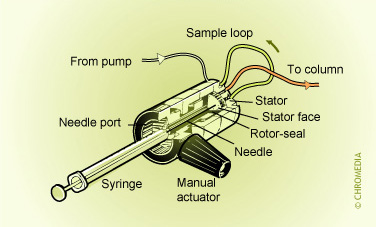
The following tubes are coupled to the six ports of the stator:
- Mobile phase inlet.
- Mobile phase outlet.
- Sample inlet: this is the port where the sample can be introduced into the valve by manual syringes, gas pressure, or pumps.
- Waste. If excess sample is injected, it leaves the valve via this port. In practice there is a small waste vial connected to this outlet.
- Sample loop. Two ports are used for the connection of this external sample loop. The volume of this loop is the maximum sample injection volume.
Valco injection valve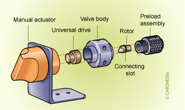
The sample loop can be loaded with the sample in two ways:
- Complete filling. This method is simple. The loop is flushed with an excess amount of sample. For best quantitative results, the volume of sample puched into/through the loop should be more than two times the volume of the loop. The injection volume can be changed only by replacing the sample loop. The commonly used injection volumes (10 and 20 µl) are typically well under the maximum allowable sample volume for standard 4.6 mm ID columns. As a rule of thumb, the sample volume should be less than 5% of the column's mobile phase volume.
- Partial filling. The loop can be partially filled with a specially calibrated syringe or sample pump. In this way, any volume between 0.1 µl and the volume of the loop itself can be injected. Injection volume reproducibility is quite good with modern autosamplers, which can achieve RSD's of less than 1%. Although this method is still quite accurate, complete filling is preferred when possible.
- First the rotor is turned into the load position. The sample loop can be filled by means of a syringe without exposure to the high pressure of the HPLC mobile phase flow, which continues to flow from pump to column through another portion of the valve. Excess sample passes out of the valve and into a waste container.
- The valve is then rotated into the inject position. The sample loop is connected in series with the supply line. The contents are transported to the column by the mobile phase under high pressure. The valve remains in the inject position for the remainder of the analysis.
Switch positions of valco valve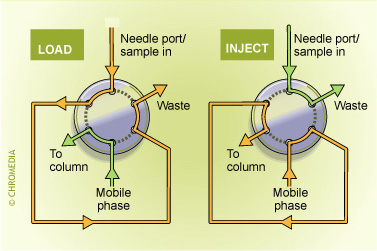
Switch positions of rheodyne valves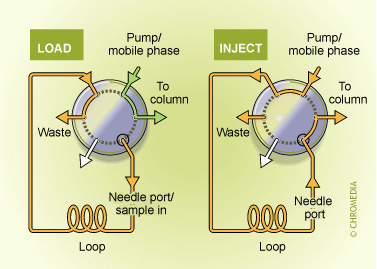
During switching, the liquid flow path is interrupted while the pump continues to run. This raises the pressure. The longer the interruption lasts, the higher the pressure becomes. Most columns cannot handle high pressure pulses. Therefore, the rotor should rotate quickly to keep the momentary disruption of the volume flow and the resulting pressure pulse as small as possible. Rotation of the valve must be completed within 0.5 seconds.
Autosamplers
The injection of samples can be automated. An autosampler can inject different samples in a predetermined sequence. The samples are put into small vials and capped with a septum. This prevents the evaporation of the liquid and possible external contamination. The vials are placed into numbered positions on the autosampler carousel in the desired order.
At the start of each analysis, the sampler needle is automatically positioned over a predetermined vial and the septum is penetrated. In general, the autosampler needle consists of a large needle in which a smaller needle is placed concentrically. Only the small internal needle approaches the bottom of the vial to actually draw up liquid.
The following parameters can be set:
- Run time (= analysis time, the system receives a start and stop signal from the autosampler)
- Injection volume
- Number of injections per sample
- Number of needle wash and flush steps prior to injection
- Allocation of an identification code to a chromatogram