Abstract An important prerequisite of the Rapid large volume injection technique is that the sample volume to be injected 'fits' in the liner. Expressed more accurately, the packing material in the liner should have sufficient capacity to retain the volume to be injected. If the sample volume exceeds the volume capacity of the liner, the Rapid 'at-once' technique can no longer be used. In this case one has to resort to the multiple Rapid method or the speed-controlled large volume injection method.
LevelAdvanced
As the multiple Rapid method is simply a combination of the multiple injection technique and the at-once method it is not discussed here. In the PTV speed controlled large volume injection technique the sample is introduced into the liner at a constant, and controlled rate. During sample introduction the liner is kept at a low temperature and the split exit is open. Upon injection of the sample a liquid film of sample is created on the wall of the injector or on the packing material. This film starts to evaporate from its top side. The sample vapours formed are discharged from the injector via the split exit. After the entire volume is (slowly) injected, there is a short wait time prior to closure of the split exit. This time is called the 'additional solvent evaporation time'. In this additional evaporation time the small volume of liquid present in the liner is given time to evaporate. After the additional solvent evaporation time the split exit is closed and the injector is heated. Typical sample introduction rates vary between 25 and 250 µl per minute. The introduction of 100 µl hence can take up to 4 minutes. Because the components are retained in the liner during the entire time required to introduce the large volume and the actual introduction only takes place when the injector is heated, the long time required for sampling has no adverse effects on the injection bandwidth of the components. When using the speed controlled sampling mode the actual volume of liquid present in the liner at each time is very low. Hence, with this mode of large volume injection PTV liners with low internal diameters can be used. This in contrast to the situation with the Rapid injection mode where larger liners are advantageous because of their larger volume capacity. An advantage of narrow liners is that the splitless transfer of the sample components after elimination of the solvent is faster. This means that speed-controlled sampling is the preferred technique where unstable analytes are to be analyzed.
When using the speed controlled PTV large volume injection method, the volume that can be injected is not restricted to a maximum. During sample introduction a steady state is reached. In this steady state or equilibrium state the speed of introduction of the liquid sample into the liner equals the evaporation rate. Liquid is introduced at the top of the injector at a rate equal to the evaporation rate. In this way a steady state situation is created. This steady state is described by the following equation:
Liquid flow into the liner [g/min] = gaseous flow out of liner [g/min]
At first glance this equation might look extremely simple. Closer examination reveals however, that the system described by this equation is very complex. Many parameters affect the equilibrium state described by the equation, the most important ones being: liner temperature, nature of solvent, carrier gas flow rate, dimensions and design of liner, pressure inside injector liner etc. The equation given above can only be solved analytically by introducing a number of (sometimes unrealistic) assumptions. Figure 11 shows the solutions of the equation for three solvents at two total injector gas flow rates. For more details the interested reader is referred to literature [@]. The figure shows the relation between the evaporation rate of the solvent (y-axis) and the temperature of the injector (x-axis). To reach the steady state, the rate at which the sample is introduced should equal the evaporation rate. Unfortunately the reliability of the data shown in figure 11 is not sufficient. This means that for practical use the data shown in this figure are of limited value only. This is mainly due to the fact that in the calculations the cooling of the liner that occurs upon evaporation of the solvent is not taken into account. To include this effect a correction factor has to be introduced. In practical speed controlled large volume experiments the actual evaporation rate is roughly 3 times lower than the value obtained from figure 11. This corrected value can be used as a rough initial guess during method development for speed controlled large volume injection. Further fine tuning of the sample introduction rate has to be carried out experimentally following the procedure described below.
Evaporation rate of some widely used solvents.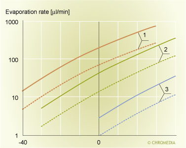 11. Evaporation rate of some widely used solvents as functions of the PTV initial temperature and the split flow rate.
Clearly, the most critical components in a PTV large volume injection are the more volatile solutes. This irrespective of which PTV large volume injection mode is used. Volatile components are easily lost during the elimination of the solvent. If these components have to be analyzed, the solvent vent conditions have to be chosen carefully. Unlike the situation in the Rapid large volume injection mode, where components with a boiling point only some 30 to 40oC above the boiling point of the solvent can be quantitatively recovered, a much larger difference in boiling points is required when using the speed controlled injection mode. Looked to it from the positive point of view: if one is only interested in components with boiling points above that of roughly C18 large volume PTV injection is extremely easy. For such a sample very often the first experiment already gives quantitative recoveries.
Optimization of a PTV speed controlled large volume injection starts with a series of experiments to establish the maximum evaporation rate of the solvent. For these experiments a standard sample containing components covering a wide range of boiling points is required. An alkane standard disolved in the solvent to be used, is generally the easiest standard, although any other sample meeting the requirement of a large boiling point range can also be used. Once the standard is selected the next point of interest is the selection of the liner. Although speed controlled injections can, in principle, be carried out using empty liners, it is usual to employ a liner containing a packed bed, in order to create a sufficiently large surface for evaporation. A small amount of packing (bed height 10 to 15 mm) in a narrow liner is generally sufficient. In contrast to the situation in Rapid injection, where the maximum amount that can be injected is directly proportional to the amount of packing, much smaller packing volumes suffice for speed controlled injections. Suitable packing materials are again glass wool or Supelcoport. If very volatile components are to be analyzed or if one wants to introduce additional selectivity in the sample introduction process an active material such as Tenax of any other GC packing material can be used. After installing the liner into the injector the split flow has to be selected. Here again the simple rule is: the higher the split flow rate the faster is evaporation. Flows are usualy set between 100 and 250 ml/min.
Next, the initial temperature of the injector should be selected. Generally a good initial value is 35 to 40C below the boiling point of the solvent. The initial oven temperature is not really important, but it is wise however, to select the initial oven temperature some 10oC above the PTV solvent vent temperature. This prevents possible recondensation of solvent vapours in the column. Once the split flow and the initial liner temperature have been selected, figure 3.11 can be used to determine the (uncorrected) evaporation rate of the solvent. The value determined this way should now be divided by a factor of three to correct for cooling of the liner. The last parameter to select is the additional solvent elimination time. In the first experiment too long a time is deliberately selected, i.e. 20 seconds. All conditions for a first large volume injection experiment are now selected.
The first real injection again is a 1 µl cold splitless injection of the standard mixture. This is the reference chromatogram. This chromatogram is recorded using the packed liner. If the components are amenable to thermal degradation or adsorption on the packing material, also a reference injection on an empty liner can be carried out. In this way possible thermal degradation or adsorption can be identified. Once the reference injection of 1 µl is completed the first large volume injection is carried out. A large volume of a sample diluted in proportion to the increase in injection volume (e.g. 125 l of a 125 times diluted standard) is injected. This is done at the conditions identified above. A comparison of the large volume injection and the reference chromatogram now indicates whether (and to which extent) components are lost. If one is only interested in relatively high boiling components (elution temperature roughly above that of n-C18) very often the first injection already gives good results. If, however, also more volatile components are of interest a more careful optimization is mandatory.
In the process of optimization of a speed controlled PTV large volume injection the recoveries that are found for volatile components relative to those found for non-volatile species are important. If poor recoveries are found for all components (both volatile and non-volatile), then liquid sample is being lost via the split exit. In this case the injection rate exceeds the evaporation rate. The solution is to now reduce the rate of sample introduction by a factor of 2. If on the other hand, only volatile components are lost, at some stage in the process of injection the injector liner is being vented to dryness. To solve this problem either the temperature can be reduced (by e.g. 10oC) or the rate of introduction can be increased (e.g. by a factor of 2). At this stage of method development the additional solvent evaporation time should not yet be reduced. At some point in method development it is seen that from the one error (only losses of volatiles) one turns into the other error (losses of both volatiles as well as non-volatiles). The optimum liner temperature (or introduction rate) occurs between these two points. Once these conditions have been identified the additional solvent elimination time can be reduced in small step to minimize losses of volatiles during this stage of large volume sampling. If too short a solvent elimination time is applied peak distortion in the middle region of the chromatogram can again occur (see figure 10 in the previous chapter). An example of the optimization of a PTV speed controlled large volume injection is given in figure 12.
Example of optimization of TV speed controlled LVI.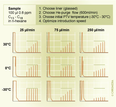 12. Example of the optimization of a PTV speed controlled large volume injection (100 µl of a standard containing n-alkanes C13 to C18 in hexane).
Even after careful optimization of a speed controlled PTV large volume injection, it will prove extremely difficult to avoid the loss of volatile sample constituents. When hexane is used as the solvent, only components with boiling point above that of roughly n-C13 can be recovered quantitatively in a speed controlled injection. Solutes with lower boiling points will, even under optimized conditions, be (partly) lost. In general, however, the losses that occur are reproducible, which implies that also solutes that are partially lost can be analyzed accurately.For experienced users there are different methods to minimize or eliminate losses of volatiles in PTV (speed controlled) injection. A first method is the use of a liner packed with an active adsorption material. This material will than (selectively) retain the components of interest. Well known active packing materials are Tenax, Volaspher, Carbotrap etc. When using these materials it should be realised that they limit the possibility to analyze high molecular weight solutes. For example in case of Tenax it will be very difficult to desorb components above roughly n-C30 at the maximum desorption temperature the Tenax allows. A second possibility to minimize losses of volatiles is by the use of a so-called 'keeper' or 'co-solvent'. This is a higher boiling solvent that is added to the main solvent in a relatively low concentration (e.g. 5%). The co-solvent forms a stable liquid film in the liner that only slowly evaporates. Volatile components will be effectively retained by this film.
 Did you ever try to explain separation to your employees or students? Well, try no more: Lee Polite did it for you in a way which is hard to beat. We will open up one example of his whiteboard class. Click this link to watch the video. To see more, you can register here. Students and teachers can access free for one month. The links in the center column lead to hundreds of chapters with text, video presentations, visualisations and animations. The chapters on Analytical Chemistry 2.1 (David Harvey), as well as basics LC, GC (Harold McNair, Lee Polite and other experts) and spectroscopy chapters are on the level of colleges, laboratory schools and universities, all 'deeper' clicks lead you to more advanced knowledge on analytical techniques with all the details for in-depth understanding for professional users.
Chromedia is used globally by numerous colleges, universities and industries, our authors are ranked as the finest teachers in the world. So go ahead and discover Chromedia by getting a 30 days subscription, which is free for students and teachers. Chromedia functionalities work best on the Chrome browser. - Our expert team
- The Analytical Scientist
- American Chemical Society
- Wiley:
- separationsNOW
- spectroscopyNOW For full access to Chromedia: click here for a paid subscription.