Abstract Capillary gas chromatography (GC) is one of the most powerful tools in modern analytical chemistry. It offers high-resolution separation, highly sensitive detection and relative ease of use. Due to its ease of use and wide acceptance, many researchers consider GC to be a mature technique, and the excellent column, detector and data system technologies that are now available would support this. However, sampling remains a fundamental and often difficult problem in capillary GC analysis. Placing appropriately sized samples onto a capillary column efficiently and reproducibly is not trivial; it requires technique and thought. In this guide, the techniques for injecting liquid samples in capillary GC are discussed, with an eye toward practical analysis, troubleshooting and method development. This guide is aimed at the analyst who is working at the bench, using GC to solve tough problems.
1. Introduction.
This introduction (2 through 8 in the left column) describe the basics of the techniques that involve syringes as the sampling device. Other methods, such as on-line extractions, SPME, sampling valves and other special techniques can be found elsewhere on Chromedia. Programmed temperature and large volume injections can be found in this Topic Circle, in the blue column on the left.
In this introduction, the fundamental problems involved with sampling into capillary GC columns are presented, along with an overview of the readily available inlets. Split, splitless and on-column injection are presented in separate chapters. Splitless injection requires special emphasis, as it is the most commonly employed technique for trace analysis, yet its fundamental principles are mysterious to many analysts.
Throughout Chromedia, the word injection is used to signify the entire process of placing a sample into a capillary column, from the syringe to the column. An injector is the device (manual syringe or auto-sampler) that performs the physical task of transferring a sample to a GC. An injector may either be a person operating a syringe or may be an robotic or automated device, also operating a syringe. An inlet is the device in the GC that receives the sample and transfers it into the capillary column.
Feel free to suggest topics or send me your questions.
Nick Snow
When packed-column gas chromatography was developed in the 1950’s, injection was a relatively simple matter. As seen in Figure 1, showing a syringe needle inserted directly into a length of ¼ inch outside diameter copper tubing, syringe needles easily fit within the bore of a ¼ or 1/8 inch outside diameter column, without modification. A typical packed column inlet simply involved providing gas flow into the tube, plus a septum and insertion point for the syringe needle, shown in Figure 2. Therefore, when a syringe is used to inject a sample onto a packed column, the entire amount of material that leaves the syringe enters the column, and other than a septum, there are no special valves or pneumatics required.
1. syringe needle inserted into a 1/4" O.D. packed column end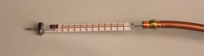
2. sample injection into a packed column inlet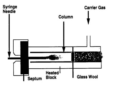
2.1 The Syringe Problem
With the development of capillary columns, the first fundamental problem occurred, and is illustrated in Figure 3. The syringe needle no longer fits within the column. Thus, a special injection chamber had to be developed. In this chamber, the sample must be vaporized and transferred to the column and re-condensed into the stationary phase at the head of the column. There has been a huge amount of research and development effort since the inception of capillary gas chromatography toward meeting this challenge without degrading or significantly altering the composition of the sample. 3. syringe needle and capillary column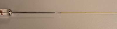 Note: needle does not fit into the column
2.2 The Column Overload Problem
Second, there is a column overload problem. Packed columns contain grams of stationary phase material. A 1 microliter liquid sample weighs a total of about a milligram. Thus, with a packed column, overloading the column with too much sample is rarely a problem. In fact, packed columns have often been used for preparative separations of milligrams to grams of analyte. However, only a few milligrams of stationary phase material are present in an entire capillary column. This means that a 1 microliter liquid sample has a similar total mass to the stationary phase in the entire column. If it is assumed that an injected sample must land in the first meter of the column and be dissolved there, it is reasonable to imagine that the injected sample, if completely transferred to the column, would easily overload the available stationary phase. This problem necessitated the development of the inlet splitter and split injection, and significantly complicated the pneumatics required for GC. It should be noted that the smallest liquid volumes readily transferred with traditional syringes are about 0.1-1 microliter; any smaller samples require special equipment. A comparison of the typical sample and injection sizes for packed and capillary GC, which lead to this problem, is presented in Table 1.
| Column Type | Liquid Sample Size (mL) | Gas Sample Size (mL) |
| ¼” Packed | 1-10 | 1-5 |
| 1/8” Packed | 0.1-2 | 0.1-10 |
| 0.53 mm capillary | 0.1-2 | 0.1-10 |
| 0.25 mm capillary | 0.01-1 | 0.1 |
| 0.10 mm capillary | 0.005-0.1 | 0.01 |
*Note the very small volumes required for small diameter capillary columns.
2.3 The Mass Sensitivity Problem
The development of inlet splitting led to yet another difficulty: the mass sensitivity problem. 1 part per million (ppm) of a 1 microliter sample (assume the solvent is water with a density of about 1 g/mL) gives a mass of about 1 ng. If it is assumed that a typical detector has a limit of quantitation of about 1 ng or in the high-picogram range, it is easily seen that GC with an inlet splitter then , in the best-case (assumes no splitting or adsprotion of sample in the inlet or column), provide about 1 ng of analyte to the detector at a sample concentration of 1 ppm. Thus, for trace analysis of samples with concentrations much lower than 1 ppm, extensive sample preparation, involving concentration of the analyte(s), is required. Many methods are therefore necessarily complicated by the need for sample preparation, more complex injection techniques, such as splitless, on-column or programmed temperature vaporization, or the need to interface the gas chromatograph to an automated sample preparation or sampling method, such as static headspace extraction, solid phase extraction or solid phase micro-extraction.
3.1 Split Inlet
Overview of split injection on Chromedia by Nico Vonk
Split injection is designed to solve the first fundamental problem: that syringes and sample sizes amenable to packed columns and easy handling by analysts are far too large for capillary columns. Basically, a split inlet allows the user to adjust the fraction of the injected sample that reaches the column by adjusting the relative flow of carrier gas through the column and through an exit valve. Split inlets are heated to ensure that the entire sample evaporates quickly as it exits the syringe needle and mixes homogeneously with the carrier gas. Split injection is the classical capillary GC injection technique and is by far the simplest for relatively concentrated (ppm and higher) samples. In a typical split injection a 1 microliter sample might be split such that 20 nL enters the capillary column (a split ratio – defined in detail later of 50:1). This method suffers tremendously from the mass problem. Due to high flow rates of carrier gas through the inlet, it provides the most rapid injection and narrowest injection bandwidth and is the technique of choice for many rapid GC applications that require very sharp peaks.
3.2. Splitless Injection
Overview of splitless injection on Chromedia by Nico Vonk
Splitless injection provides a straightforward means for improving sensitivity by transferring nearly the entire analyte sample to the column, rather than splitting the bulk of it away through the split vent. Basically, splitless injection is performed using the same inlet as split injection, but by injecting with the exit valve closed, so that the injected material has no place to go but into the column. The exit is left closed for a period of time (typically 30-60 seconds) then opened to clean out residual material from the inlet. Again, the inlet is maintained at a high temperature to ensure vaporization of the entire sample. In this manner, about 95% or more of the injected materials is transferred to the capillary column. Sample overload and peak broadening are avoided through a complex series of thermal and solvent effects, which will be described in detail in Chapter 3. Splitless injection involves more complicated pneumatics than split injection, and requires more complex method development, but it does partially mitigate the mass problem. Splitless injection is currently the most commonly used technique for trace analysis (low ppm and ppb analyte concentrations), although complex sample preparation is often required, and method development can be difficult.
3.3. On-column Injection
Overview of cold on-column injection on Chromedia by Nico Vonk
On-column injection, which, as the name implies, involves the placement of the injected sample directly onto the capillary column, without a separate vaporization chamber, can be performed routinely by using a special syringe with a tapered needle. Similar to splitless injection, an entire sample is placed onto the capillary column and the analytes are separated from the solvent through solvent and thermal effects. Unlike split and splitless, on-column injection is performed using a cold inlet. Because the sample is placed directly into the column, there is no room for vaporization, and this is not necessary. The inlet is heated along with the column as a temperature program is performed. On-column injection requires special syringes and techniques that may not be practical for all analysts and situations, but it is the technique of choice for the best quantitative analysis. Dirty samples are problematic, as the entire sample is transferred to the column, which leads to column fouling and additional system maintenance. Solvent vapor exit, a specially modified on-column injection technique allows the injection of very large volumes (up to hundreds of microliters) of dilute samples.
3.4. Programmed Temperature Vaporization
Overview of PTV on Chromedia by Hans-Gerd Janssen
The idea of cold injections was extended to split and splitless injection in the 1970s and 1980s by modifying a classical split/splitless inlet to accommodate temperature programming. Similar to on-column injection, this injection is performed cold, however, the inlet is then rapidly temperature programmed to transfer the injected analytes to the column. Cold injection offers several advantages in performing quantitative sample transfers to the column and also allows the injection of very large volumes (ealisy up to 100 microliters all at once). There are numerous modes in which a temperature programmed inlet can be operated, perhaps making it the most versatile inlet available. The versatility of a PTV inlet is also its greatest challenge; there are many parameters to optimize and control for effective injections.
Discussion of techniques for PTV-Large volume injection on Chromedia by Hans-Gerd Janssen
Choosing the correct inlet and injection technique is one of the most important decisions in gas chromatographic method development. It is possible that more than one inlet may be appropriate for a given sample, or it is even possible that no inlet, without significant additional sample preparation is appropriate. A decision matrix for choosing an appropriate inlet to begin method development is shown in Table 2. Choosing an injection method is not trivial and can be very difficult.
Of the three classical methods, split, splitless and on-column, on-column is the preferred technique from the fundamental perspective, although it is not widely used, due to its many practical difficulties, especially that the entire sample, including all impurities, enters the column. Splitless is often substituted as a practical alternative for on-column, although there can be problems with injecting high molecular weights, polar compounds or thermally labile compounds. Several sample types are not amenable to any of the classical methods. These would require further sample preparation and concentration, or the use of a large volume injection technique. Programmed temperature injections can mitigate the problems with classical splitless injection, while still allowing a splitless injection to be performed.
| CONCEN-TRATION | STABILITY | BOILING POINT | SOLVENT | STARTING TECHNIQUE |
| Percent | High | Low | Polar | Split |
|
|
|
| Non-polar | Split |
|
|
| High | Polar | Split |
|
|
|
| Non-polar | Split |
|
| Low | Low | Polar | On-column, PTV |
|
|
|
| Non-polar | On-column, PTV |
|
|
| High | Polar | On-column, PTV |
|
|
|
| Non-polar | On-column, PTV |
| ppm | High | Low | Polar | Split |
|
|
|
| Non-polar | Split |
|
|
| High | Polar | Split, splitless |
|
|
|
| Non-polar | Split, splitless |
|
| Low | Low | Polar | On-column, PTV |
|
|
|
| Non-polar | On-column, PTV |
|
|
| High | Polar | On-column, PTV |
|
|
|
| Non-polar | On-column, PTV |
| ppb | High | Low | Polar | On-column |
|
|
|
| Non-polar | On-column, splitless |
|
|
| High | Polar | Splitless, PTV |
|
|
|
| Non-polar | Splitless, PTV |
|
| Low | Low | Polar | On-column |
|
|
|
| Non-polar | On-column |
|
|
| High | Polar | On-column, PTV |
|
|
|
| Non-polar | On-column, PTV |
| Sub-ppb | High | Low | Polar | Concentrate then on-column |
|
|
|
| Non-polar | Concentrate then on-column, splitless |
|
|
| High | Polar | PTV |
|
|
|
| Non-polar | PTV |
|
| Low | Low | Polar | ? |
|
|
|
| Non-polar | ? |
|
|
| High | Polar | PTV |
|
|
|
| Non-polar | PTV |
Before moving to a discussion of specific inlets and injection techniques, it is necessary to briefly discuss some general good practices and proper operating procedures for capillary gas chromatographs, as many ideas involved with gas chromatograph operation have effects on inlet performance.
Scheme of a universal GC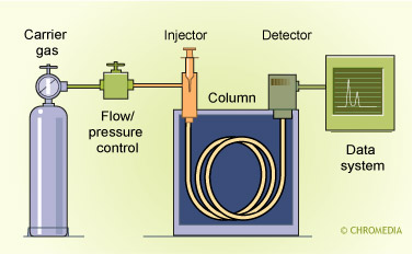 A schematic of a typical GC system is shown above, with the areas critical to inlet operation highlighted. Even the detector choice gets involved, as the use of a mass selective detector involves placing a high vacuum at the end of the column, having a major effect on the gas flows.
A photograph of an open gas chromatograph oven is shown in Figure 5.
5: interior of a GC column oven showing the capillary column, inlet and detector connections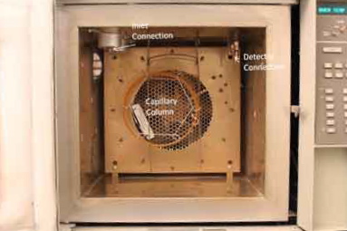 Key points requiring careful installation and work include the inlet and detector column connections, the choice of column dimensions (length, inside diameter, stationary phase and film thickness) and the specific procedures used to install the column. One key to successful injection is proper column installation.
Overview of column installation at the inlet on Chromedia by Nico Vonk
Overview of GC instrumentation on Chromedia by Nico Vonk
First and foremost, “capillary GC is clean GC” (Stuart Cram and Milos Novotny, ACS Short Course, 1988). Many of the problems and compromises, such as packing in the inlet liner and sample splitting, involved in sample introduction, are related to ensuring that the samples reaching the capillary column are “clean.” It is important to ensure that carrier and detector gas supplies are of the cleanest grade available and that they are connected to the GC using two-stage regulation with stainless steel diaphragm, as polymeric diaphragms often allow leakage of contaminants from the atmosphere. DO NOT use “Snoop” or soap solutions for leak testing capillary systems; these will diffuse into the gas stream and can appear as ghost peaks. The carrier gas supply should also be passed through an appropriate scrubber to remove impurities such as air, water and hydrocarbons. Any scrubbing system should be monitored carefully to ensure that it does not become overloaded or dirty. An overloaded scrubber can actually be worse than none at all, as adsorbed impurities can be desorbed directly into the GC. Scrubbers should be located as close to the GC bulkhead fittings as possible, to eliminate the possibility of leaks or contamination. A summary of scrubbers is provided in Table 3.
| Type of scrubber | Application |
| Molecular sieve | Removes low molecular weight impurities, such as air and water |
| Carbon black | Removes organic impurities such as hydrocarbons |
| Drying agents (Drierite, etc.) | Removes water |
| Heated purifiers | Can remove all impurities with a single cartridge; generally expensive, difficult to monitor overload; not appropriate for hydrogen |
| Integrated | Some gas vendors provide a scrubber integrated inside the gas tank; advantage is convenience |
Today’s capillary GC systems employ microprocessor-controlled pneumatics, although many GC’s more than 15 years old employ the classical manual systems. Microprocessor-controlled pneumatics, often called electronic pressure control (EPC) or electronic pneumatics control, EPC, offer more flexibility, as pressures and flows can be changed during the run. Manual systems are generally limited to the pressure or flow conditions at the start of the analytical run. This can be important, as volumetric flow rates of gases decrease as the gas temperature is increased, due to a change in the gas viscosity. With an electronically controlled system, it is often preferable to conduct the injection at an elevated pressure, followed by a decrease in the pressure to an optimum value for the GC column during the run and to increase the pressure throughout a temperature3 programmed analysis to maintain a constant volumetric flow.
The syringes used for GC injections require special mention, as they are critical to successful performance of any of the sampling devices described in this guide. Syringes for liquid sampling are generally made from glass, with stainless steel components and are generally inert. Before performing an injection or beginning a sequence with an auto-injector, you should ensure that the syringe is free from defects, including bends in the needle, leaks and contamination that may cause poor plunger operation. The syringe should be rinsed several in the solvent being used for the analysis, both before and after the injection. Figure 6 shows several syringes used for gas chromatographic injections. The 1-10 microoliter syringe at the top is the mainstay. Also commonly used are smaller volume plunger-in-needle syringes (middle) and gas tight syringes (bottom).
6: typical syringes for manual injection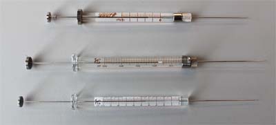
Loading the syringe for manual injection requires practice. One way to learn the basics is to carefully observe a fast auto-injector: try to emulate its motions. To properly load the sample, the needle should be placed into the sample below the liquid level. Leave the vial upright; do not invert it as your doctor would with loading a syringe in the hospital, as seen in Figure 7. 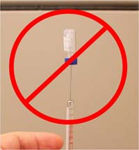 To remove an air bubble from the syringe, work the plunger several times, with the sample. This should force the air bubble out the needle. Due to the narrow bore of the barrel, it is difficult to remove an air bubble by inverting and tapping the glass. Pull-up sample liquid to a volume greater then that needed and remove the needle from the sample vial. Invert the syringe and push out the excess sample, gently cleaning it from the needle with a dry laboratory wipe. For most injection techniques, you can then inject the sample rapidly and begin the GC run. Specific syringe operation considerations will be described for the individual inlets and injection methods. In most cases, a fast auto-injector is the best syringe handling device.
Most inlets use a polymeric septum to allow introduction of a syringe into the flowing gas stream without causing the gas, which is pressurized, to leak. Proper care and replacement of the septum is critical in maintaining a clean system, as broken septum pieces can contaminate the inlet and materials from samples can contaminate the septum and ultimately cause interfering peaks in chromatograms.
8. used and new septa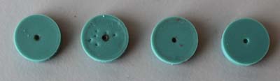 Figure 8 shows several septa. The clean appearing septum on the far right is brand new. Note that many septa today include a small hole pre-drilled in the center to facilitate needle penetration and to reduce degradation from multiple injections. The three septa on the left are all used and in varying bad conditions. Note the darkened hole in the middle of each; this is decomposed sample material left behind from the syringe needle and is one of the main sources of “septum bleed” that often contaminates chromatograms with extraneous peaks. Another source of septum bleed is septum material that breaks off and collects inside the inlet. Generally the septum should be changed every 30-50 injections or before beginning long sample sequences.
For ease of operation and maintenance, a large supply of consumables should be maintained. Many of these items are specific to a given inlet, so be sure that you are using consumables designed for that inlet. These include, but are not limited to septa, glass liners, o-ring seals, graphite or graphitized vespel ferrules, glass wool, and packing materials (when using a PTV inlet, especially), plus a toolkit appropriate for inlet maintenance. Many instrument and supply vendors offer complete maintenance kits for both inlets and detectors.
Making the proper connections in a capillary GC system is critical and is also something of an art. When installing a column, check to be sure that the ends of the column have been cleanly cut; the column vendors can provide details on procedures for this. Examples of good and bad capillary column cuts are shown in Figure 8. When making connections using graphite or graphitized vespel ferrules, finger tight is often tight enough to produce a leak-free seal. You should never have to tighten a graphite ferrule more than finger tight plus ¼ turn with a wrench. If you do, then the connection hardware may need replacement. When using connectors, beware of old material that may be lodged within the connector; be sure it is clean. Ideally, brass and stainless steel fittings should also be tightened to finger-tight plus ¼ turn.
Once a column is installed and the carrier gas supply is connected and turned-on, check for leaks using an electronic leak detector. DO NOT use soap solutions or sprays to check capillary GC systems for leaks. Soap material will diffuse into the tubing and may later produce “ghost” peaks or contamination, or damage to the column. Remember that capillary GC is very sensitive to any source of contamination. Later, in the troubleshooting chapter, you will see that many of the common problems encountered with GC set-up and chromatograms can be traced to the connections at the inlet.
The remaining chapters in this guide to follow throughout the year, provide a fundamental and practical overview of each injection technique, with a focus on assisting analysts at the bench with method development, maintenance and troubleshooting issues.